(Cement production and management issues, in a sense, lock the wind and anti-wear problem)
(Thecompany is the only one of the earliest composite wear board to dodischarge liner and use a large amount of the most complete model of thecompany (φ150-2200mm). Is the large-scale self-cleaning type unloaderuse and export The only manufacturer of multiple units !!)
Features:
1,Contact with the material are inlaid with surfacing composite wearplate (8 +6 mm), the surface hardness of HRC55-62, with bolted, wear canbe replaced.
2, with hot air duct, material viscosity can be hot.
3,in order to facilitate the replacement of dust after the wind washedparts of the site, the edge of the wheel with a removable anti-wearring, the end plate is also equipped with anti-erosion around theanti-wear ring, easy to replace, and can be replaced many times Timemaintenance.
4,the technical points: when the impeller edge wear does not appear stuckphenomenon, which is the current impeller feeder a major problem, wewill leave the impeller end of the appropriate gap, so no longer plugmaterial, which wear No more card material phenomenon, while not hot airthrough the wind, using a labyrinth seal.
5, viscous material can be ordered from the clear discharge device, and applied for a patent.
First, the structure outlined
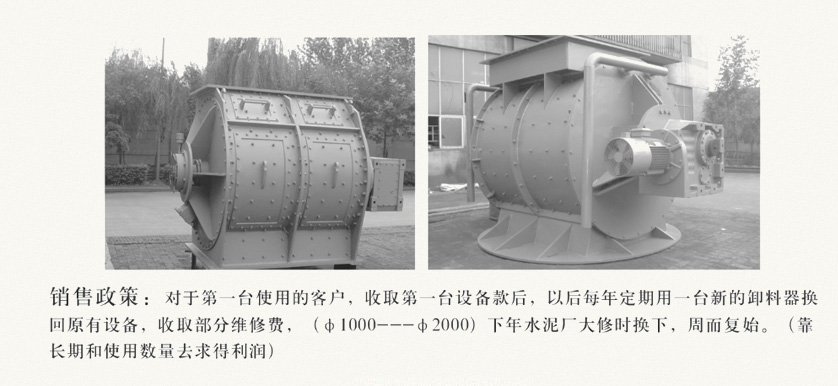
1,the impeller feeder is the company specifically for raw materials intothe mill, quantitative feeding and as a positive pressure or negativepressure delivery system designed to lock the wind feeding device.
2,the impeller feeder its simple structure, reliable performance, goodsealing performance, there can be replaced and anti-wear lining checkdoor, the structural characteristics of the provisions of the materialinto the mill can not be stuck by the size of the problem. Long-term useat home and abroad highlights the characteristics of the device -smaller size, easy to promote use.
3,the structure of the impeller feeder, including a rotating impeller, afixed shell and drive devices, impeller blades are mostly welded withanti-wear plate to improve the service life of the impeller; feedingcenter distance and the shell centerline A certain deviation is intendedto apply to the entry of larger particles of material. Shell liner isequipped with anti-wear layer; Impeller is supported by both ends of thebearing, the impeller and the shell can guarantee the gap between theuniform; due to the higher feed temperature, leaves and leaves the gapbetween the shell. Sealing at both ends is sealed with asbestos packing,the way is simple, good sealing, easy to operate and replace.
Thisunloader is equipped with hot air channel, when the feed humidity, theimpeller may be a certain thickness of the end of the sticky powdermaterial, then you should pass the higher temperature of the gas, sothat the bottom of the material dry, Then in the bottom of the impellerwill not affect the feed volume, when not in and out of the outletblindly.
Φ1800mmabove the feeder on the side of the shell to open one or two openinspection doors, if necessary, may open, check the internal situationand replace the surface of the anti-wear layer, and the impeller on theanti-wear layer. And there are inspection holes, usually when the debrisinto the impeller or blocking material and other accidents affect thefeeder normal operation, you can open the door for cleaning, or observethe specific circumstances, you can observe the feed situation, thedevice bucket Capacity is generally between 30-50%, not too much intothe material, feed conditions and through the rotation speed of theimpeller to control the device. The faster the feed rate of each bucketless, the slower the feed rate of each bucket the more control can notbe greater than 30-50%, bucket into the feed more than 50% of the easystuck, making the drive damaged.
Notethat the direction of rotation of the impeller to be marked in thedirection of rotation can not be the opposite direction to feed,otherwise there will be stuck phenomenon, impeller overload or impellerabnormalities need to be installed by the demand side of the motorprotection device (overload protection) A proximity switch, through theimpeller rotation signal, the operation of the impeller feeder tomonitor.
Second, technical performance
Atpresent, we design the raw material feed mill three size files,according to the need to design: MT600, MT800, MT1000, MT1200, MT1400,MT1600, MT1800, MT2000, feeding capacity from 80t / h-650 T / h, thenumber of revolutions from 0-27 r / min, are used torque force, smallsize of the frequency control reducer.
Atthe beginning of feeding, be sure to start from the middle speed to thematerial, the number of revolutions too fast, bucket capacity can notreach 30%, the feed is not enough; turn too slowly, fighting capacitywill be filled with the phenomenon of stuck. Grasp the specificsituation to find an objective speed, so as to achieve their own needsto feed. For example: the number of revolutions is 9 r / min, then thefeed start of the number of revolutions from 5 - 7 r / min, schedulingto the corresponding feed rate, not from the slowest start.
Raw material grinding into the lock lock wind unloader
Cement production and management issues, in a sense is the lock wind and anti-wear problems
Thecompany is the only one of the earliest composite wear plate to dodischarge liner and use a large amount, the most complete model of thecompany (φ150-2200mm). Is also a large-scale self-cleaning-type unloaderto use multiple and more than the only export manufacturers!
Features:
(1), through the hot air; the bottom of the impeller is not expected.
(2), erosion site special design, wear slow not card material.
(3), maintenance parts demolition type, then to repair.
(4), viscous material can be ordered from the clear discharge.

| φ800 | φ1000mm | φ1200mm | φ1200mm *1600mm | φ1600mm | φ1800mm | φ2000 |
density(t/m') | 1.1-1.4 | 1.1-1.4 | 1.1-1.4 | 1.1-1.4 | 1.1-1.4 | 1.1-1.4 | 1.1-1.4 |
Graininess(m) | 0-80 | 0-100 | 0-100 | 0-120 | 0-120 | 0-120 | 0-120 |
Moisture(%)fluidity | 4-10差 | 4-10差 | 4-10差 | 4-10差 | 4-10差 | 4-10差 | 4-10差 |
Feeding capacity range(t/h) | 65-100 | 100-150 | 150-250 | 250-320 | 300-400 | 400-520 | 520650 |
Negative pressure inside the mill(mbar) | -60~-80 | -60~-80 | -60~-80 | -60~-80 | -60~-80 | -60~-80 | -60~-80 |
Rotor diameter(mm) | φ800 | φ1000 | φ1200 | φ1200 | φ1600 | φ1800 | φ2000 |
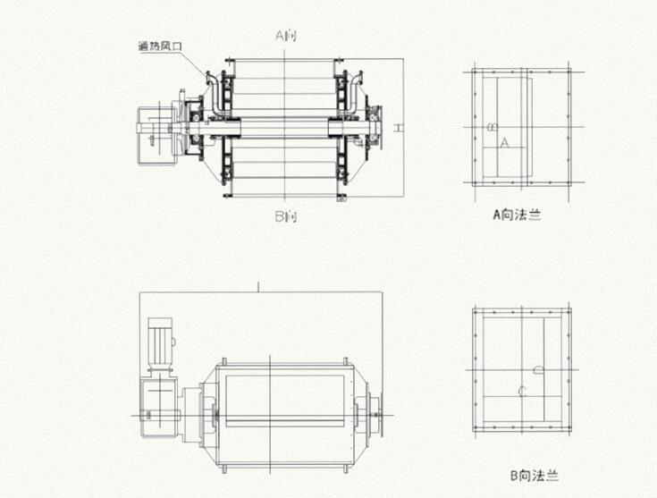
equipmentHXL (mm) | 1100X2025 | 1400 X2492 | 1600 X2463 | 1600 X2863 | 2000 X3030 | 2300 X3555 | 2450 X3546 |
Inlet size(axbmn) | 700 X450 | 1010X450 | 1000X500 | 1400X500 | 1226 X675 | 1600 X785 | 1640 X900 |
Outlet size(axdmm) | 800 X800 | 1000x800 | 1050X1210 | 1450X1210 | 1440X1440 | 1670X1410 | 1850X1600 |
Applicability(t/h) | 80 | 130 | 220 | 280 | 320 | 450 | 650 |
Rotor speed(r/rnin) | 0-13 | 0-13 | 0-12 | 0-12 | 0-7. 8 | 0-7. 1 | 0-7.6 |
Fill proportion(%) | 33-50 | 33-50 | 33-50 | 33-50 | 33-50 | 33-50 | 33-50 |
Rotor end line speed(m/s) | 0.84 | 0.68 | 0.75 | 0.75 | 0.65 | 0.63 | 0.7 |
Reducer model | GKAF117-7.5-4P -115-M1-B-1 | GKAFL27-1L-4P -119-M1-B-1 | GKAF1127-LL-4P -121-M1-B-L | GKAFL27-L1-4P -L2L-ML-B-L | GKAFL57-LL-·liP- 123.25-ML-B-1 | GKAFL67-L5-·liP -L35-ML-B-1 | GKAFL67-15-·liP -135-ML-B-1 |
Motor Power(kw) | 7.5 | 11 | 11 | 11 | 11 | 15 | 15 |
Voltage/frequency(v/Hz) | 380/50 | 380/50 | 380/50 | 380/50 | 380/50 | 380/50 | 380/50 |
Motor speed(r/rnin) | 1450 | 1450 | 1450 | 1450 | 960 | 960 | 960 |


